Overrides
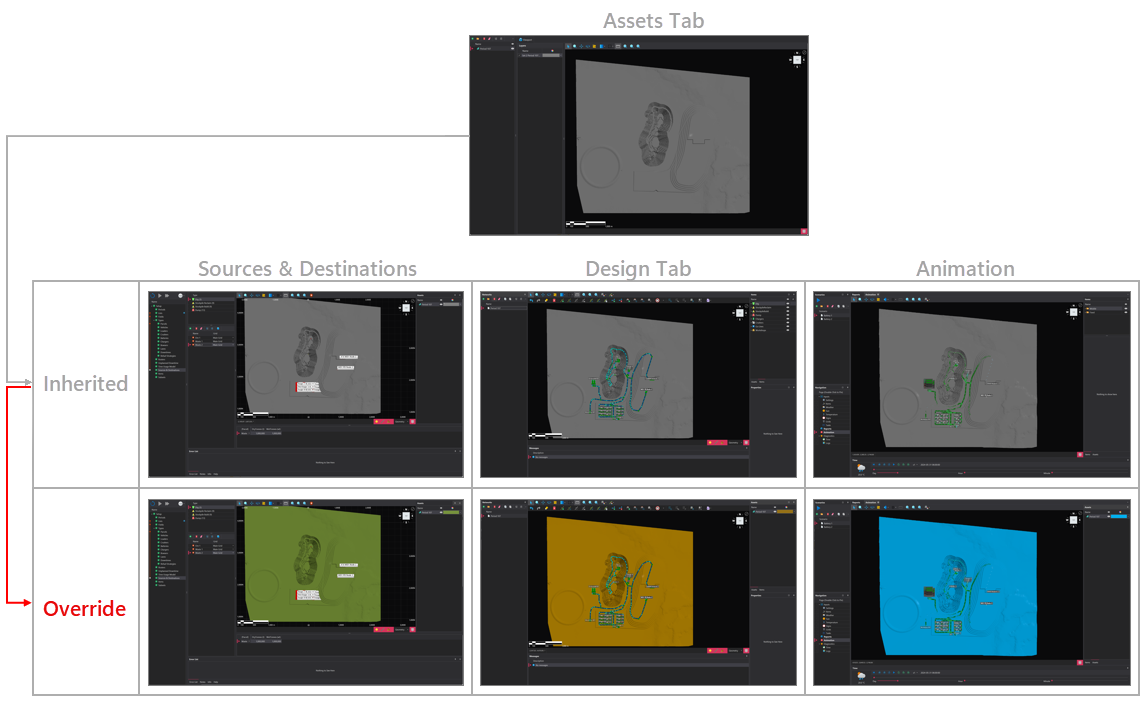
The default appearance of layers is configured in the Assets tab, and these settings are inherited by the layers throughout the software. However, appearance settings can be overridden in any downstream viewport if necessary. This workflow is shown in the image below. This page contains information relevant to both the initial appearance settings, set in the Assets tab, and any subsequent viewport within the software.
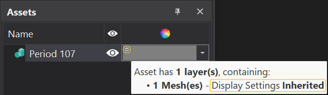
If an Asset's appearance has been overridden, you will not see the little circle with a downward arrow head in the top left corner of the color box. Alternatively, you can check by reviewing the tool tip and checking 'Display Settings'.
Mesh Files
By default, when you load a mesh file in the Assets tab, it will appear in the default colour . To override the default colour after import or to modify the initial appearance settings in a downstream viewport, enable the "Override" checkbox. Once enabled, several appearance override options will become available.
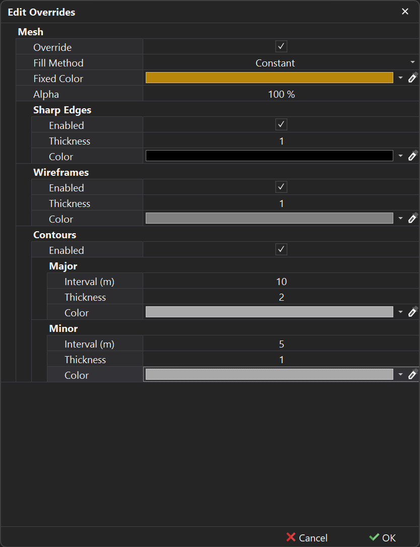
Fill Method
The Fill Method setting controls how the surface of the mesh is colored or textured, with options like constant color, slope-based shading, RL-based coloring, and image draping.
| Method | Description |
|---|---|
| None | The mesh will be displayed without any colour or texture, relying solely on the additional rendering options (detailed below), such as the wireframe. If no additional rendering options are enabled, the mesh will not be visible. 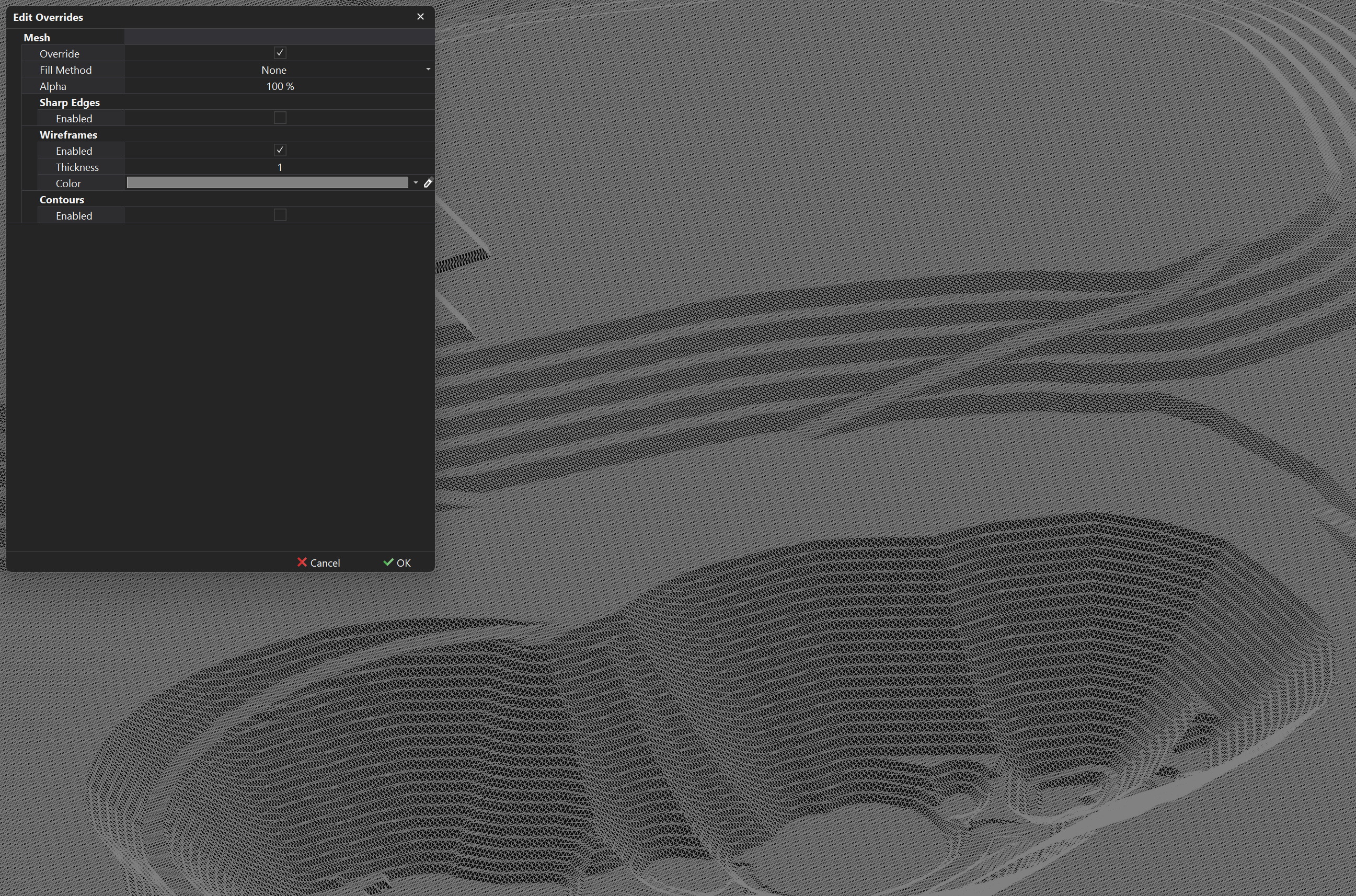 |
| Constant | The mesh will be displayed in a constant color, with the following parameters to be specified:
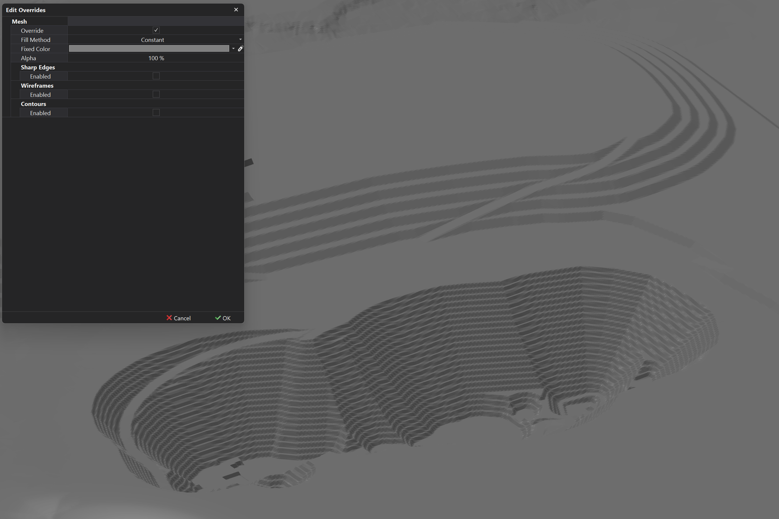 |
| Slope | The mesh will be colored based on the slope of the triangles, allowing for the visualisation of the terrain's steepness. Slope angle ranges are configurable, with each range associated with a corresponding color, to effectively highlight varying degrees of incline and decline. 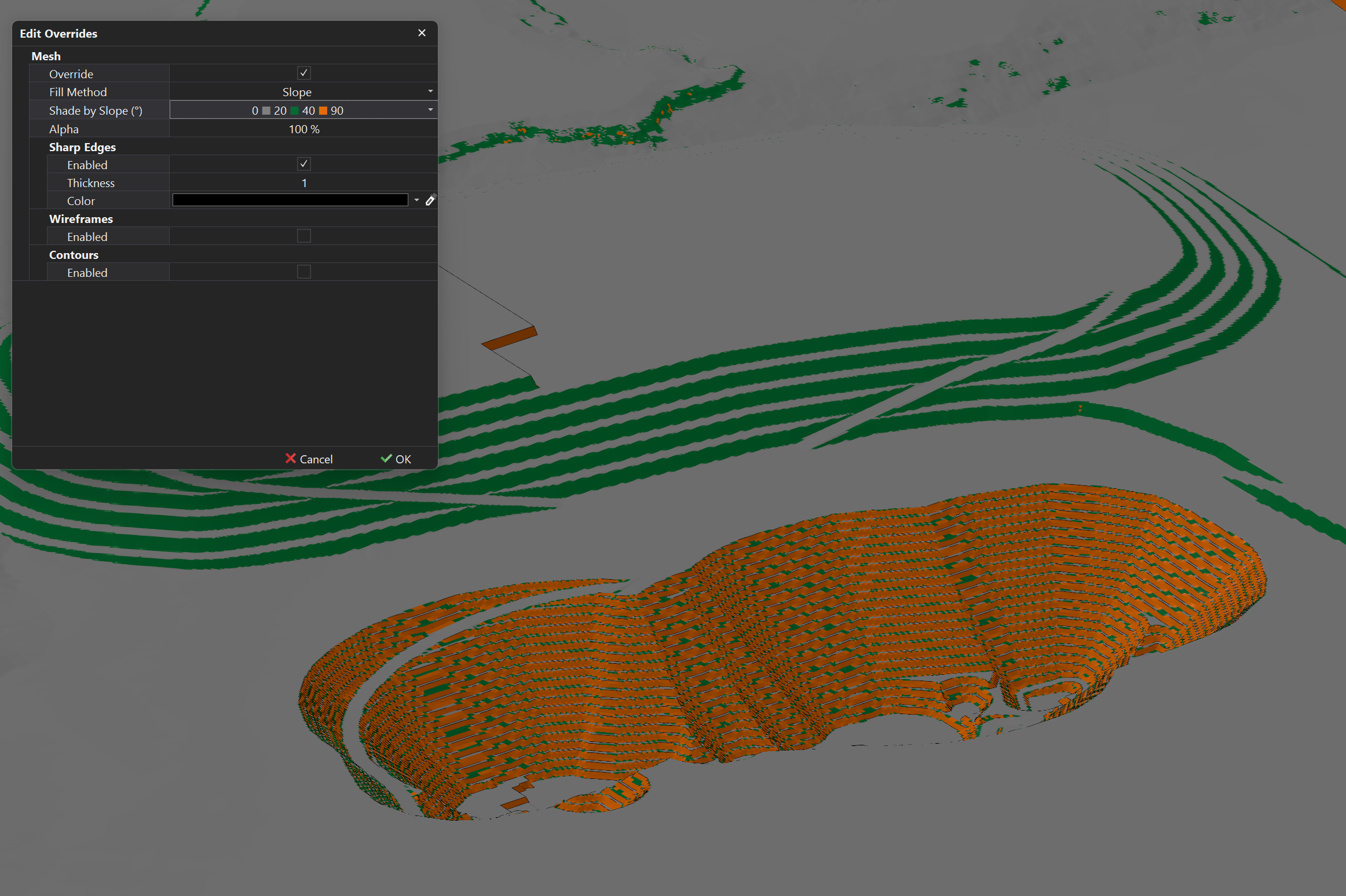 |
| RL | The mesh will be colored based on the Relative Level (RL), facilitating better interpretation of complex data, such as the current water table level and the characteristics of different rock layers, which can lead to more informed decision-making. 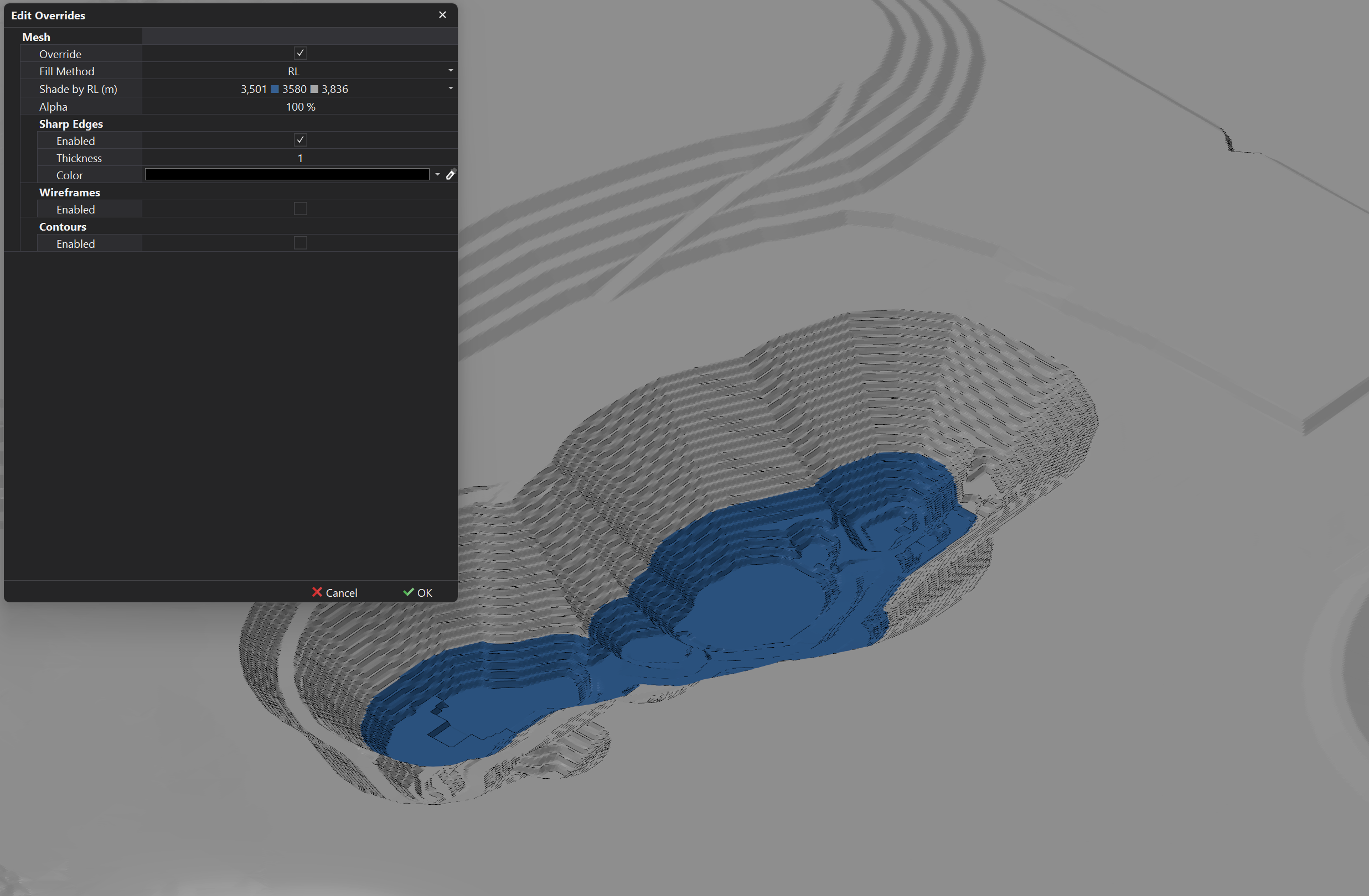 |
| Image | The mesh will be textured using a relevant aerial image, which requires mapping coordinates to align the image accurately with the mesh file. The image must be loaded in as an Asset for it to be referenced in the Drape Setup.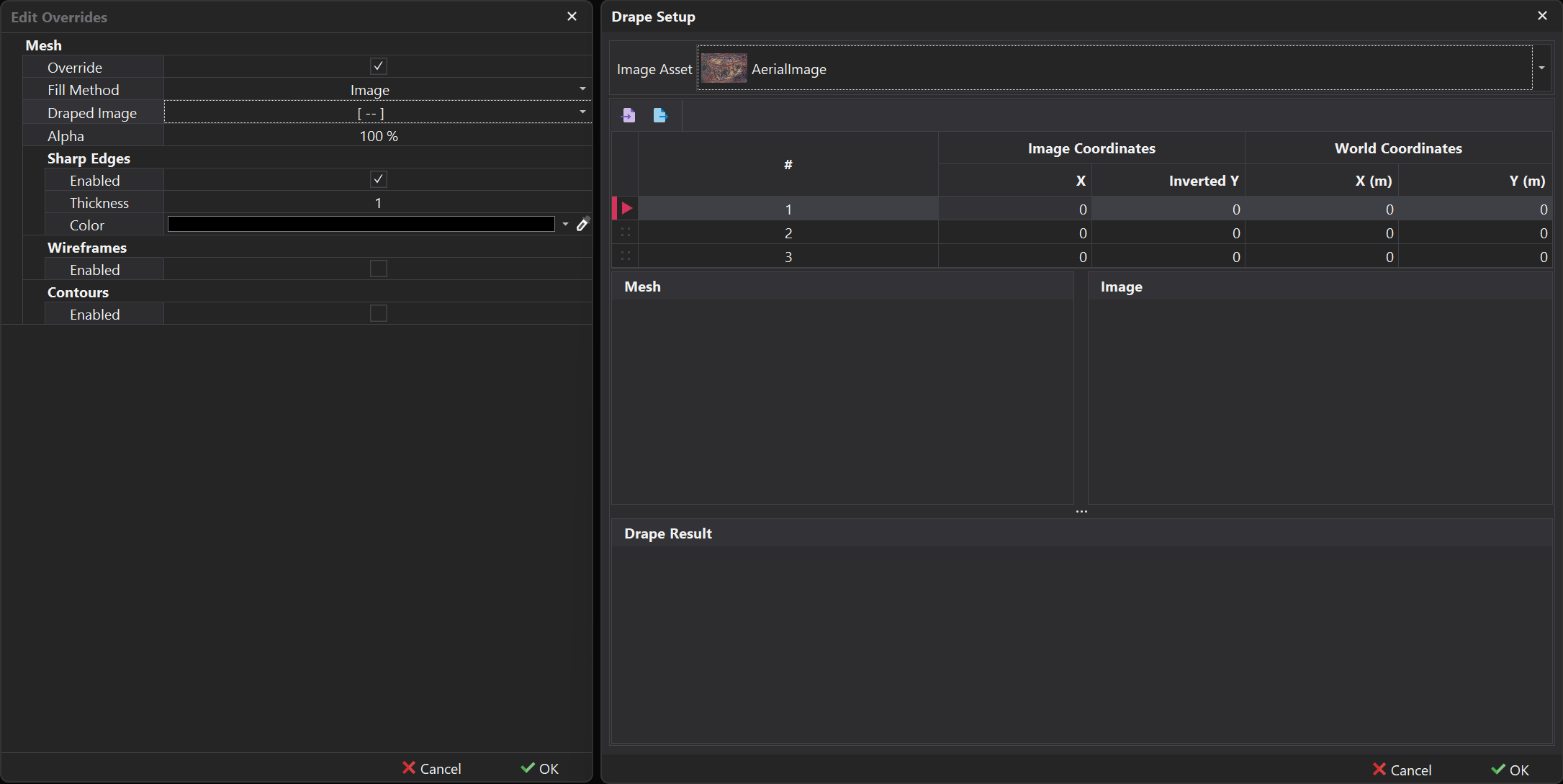 |
| Inherit | The mesh will inherit the 'Fill Method' from the initial appearance settings configured in the Assets tab, meaning only the rendering options can be changed. This setting is only useful outside of the Assets tab. |
Rendering Options
In addition to the Fill Method, other visualisation options such as Hard Edges and Contours further refine the appearance of the mesh by enhancing edge contrast and elevation details, respectively.
| Item | Description |
|---|---|
| Sharp Edges | When Sharp Edges are enabled, they visually enhance the contrast between faces that meet at a sharp angle, giving the model a more defined and crisp appearance. This can be useful for highlighting hard surfaces or features, especially in technical models, by making edges stand out instead of appearing smooth or blended.
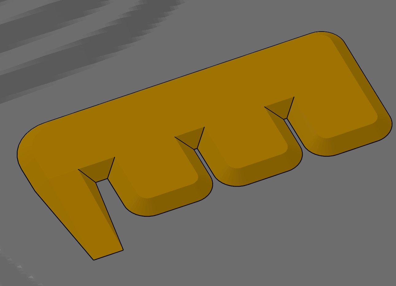 |
| Wireframes | The Wireframe setting displays the underlying triangles of the mesh file, providing a clear view of the model's structure and topology. This can be particularly useful for debugging and optimizing complex models, as it allows users to identify issues such as overlapping geometry or inconsistent surface normals, ensuring a more accurate and efficient rendering.
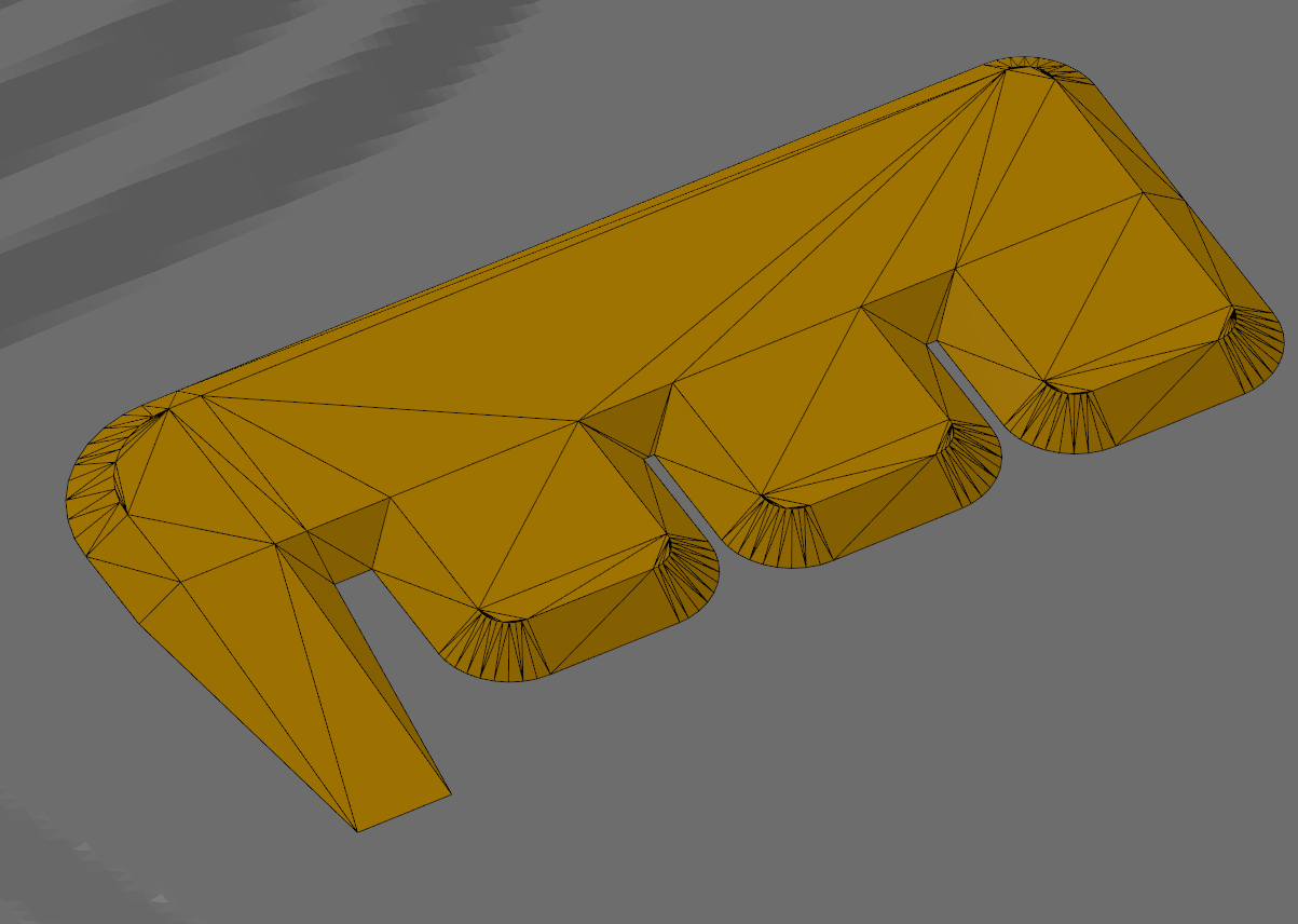 |
| Contours | The Contour setting visualises the elevation or depth changes within the mesh, enhancing the understanding of the model's topography. This feature is particularly useful for analyzing terrain features and gradients, making it easier to assess landforms, slopes, and other geological characteristics that may impact design or operational decisions.
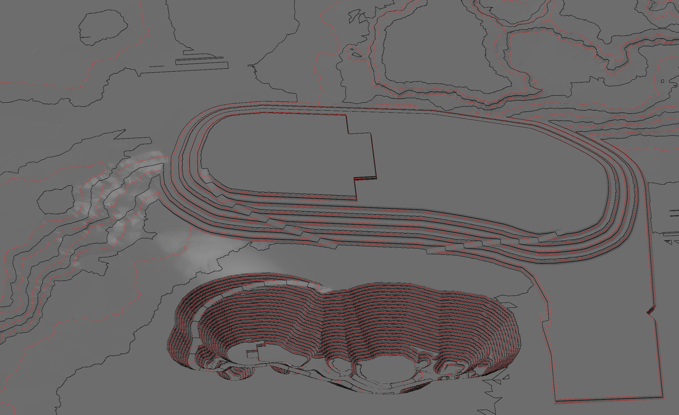 |
Polylines, Polygons, Points
By default when you load in Polylines, Polygons or Points, they will appear in there default color which is typically white and with a thickness of 1. To override these parameters, the "Override" checkbox needs to be enabled. Once enabled, the following appearance options will become available.
Appearance Properties

| Property | Description |
|---|---|
| Thickness | Specifies the width of the polylines, allowing you to adjust their prominence in the visualisation. |
| Color | Defines the color of the polylines, enabling you to customise their appearance for better distinction. |